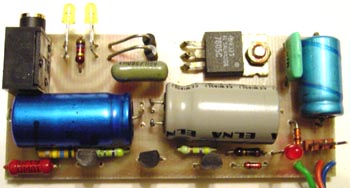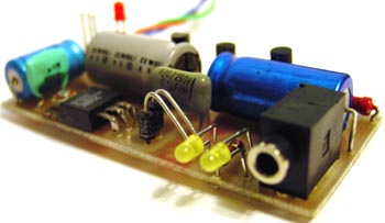
Assembling |
ICT upgrade |
Testing |
Program |
This is upgrade instructions for first IC Tester device. IC Tester 2 has already this upgrade.
Due some problems on few controllers, I decide to make upgrade on IC Tester device. Problems are:
| Part No | Part Type | Amount required |
| IC6 | 7805 | 1 |
| T33, T34 | BC 547 | 2 |
| T35 | BC 558 | 1 |
| D1, D4 | 1N4148 | 2 |
| D2, D3 | 1N4002 | 2 |
| LED3 | Red, 3 mm | 1 |
| LED4, LED5 | Yellow, 3 mm | 2 |
| R8 | 5,6 kOhm | 1 |
| R42 | 75 kOhm | 1 |
| R43 | 560 kOhm | 1 |
| R44, R45 | 470 kOhm | 2 |
| R46 | 100 Ohm | 1 |
| R47 | 56 Ohm | 1 |
| C1 | 330 uF/10V (microF) | 1 |
| C2, C3 | 470 uF/25V (microF) | 2 |
| C4, C5 | 100 nF | 2 |
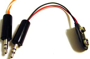
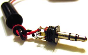
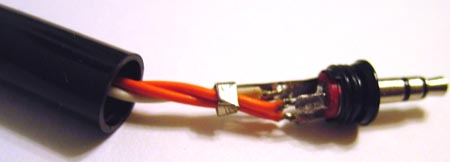
| CONN2 | 3,5 mm stereo headphone jack | 1 |
| CONN3 | 3 pin male single lined connector | 1 |
| Other | Piece of wire to make short connection from R47 to IC5 | 1 cm |
| Other | 3 wires | 12 cm |
| Other | 3,5 mm stereo headphone connector | 1 (2) |
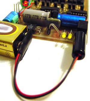
| Other | 9V power connector | 1 |