Assembling |
OCR addon |
Testing |
Program |
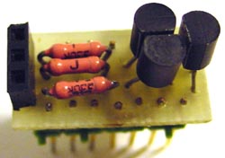
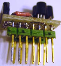
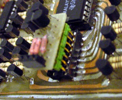
This is assembling instructions for Diode/OCR addon device that is connected on test socket at IC Tester device.
With this addon you can test if regular diodes and LEDs working, which pin is what and test if OCR elements (thyristors and triacs) working.
| Part No | Part Type | Amount required |
| T1-3 | BC 547 | 3 |
| R1-3 | 330 Ohm | 3 |
| SOC1 | 3 pin female single lined connector | 1 |
| CONN1, CONN2 | 8 pin male single lined connector | 2 |
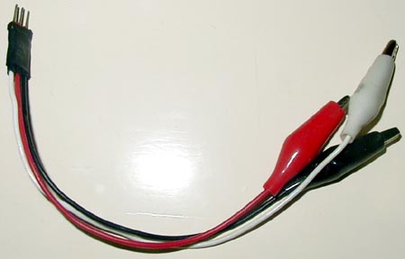
| Other | 3 color wires | 15 cm |
| Other | color crocodile clamps | 3 |
| Other | 3 pin male single lined connector | 1 |